I am working on my own car charger. The main goal is to get some hands on experience, refresh some of the stale knowledge and skills, and well have fun.
It is important to note here that the resulting design will definitely be less safe and probably more expensive than commercial boxes.
Videos
I’ve put together a few videos on this topic, so feel free to check them out if you prefer that format.
The one that inspired this post is the design one:
V1 – The simplest charger
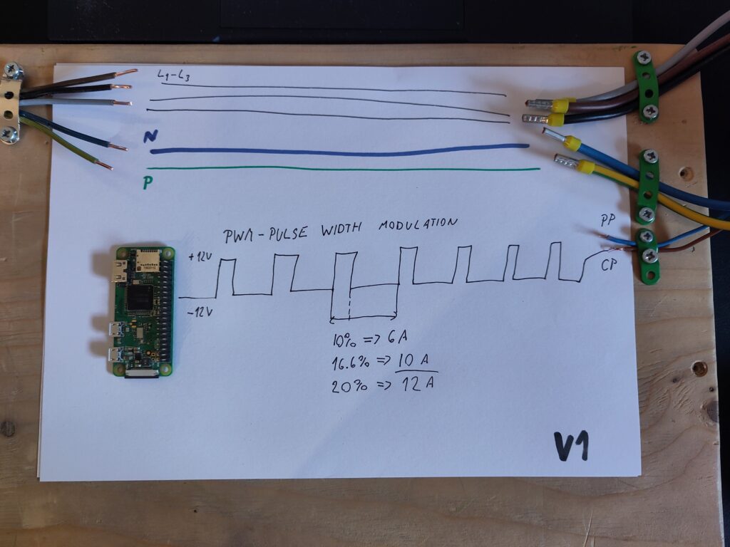
The diagram above shows the EV charger socket on the right and its wires attached to a wooden plank. On the other side, we have wires representing line power from my power box.
AC connections
The simplest thing we could do is connect left to right. So, connect power lines (3 phases in this case), neutral, and protective earth straight to the pins of the charging cable socket.
That idea might seem kind of out there, but that is exactly how any other device or electric load in our home is connected. The power socket for your laptop charger or fridge is wired that way. The only difference is that those are one-phase loads, so they would have only one L wire instead of three.
Sadly, this would not be enough for our purpose. EVs can pull quite a significant effect from our home electric lines. In our home specifically, it is by far the single biggest consumer of energy. Such high effects can pose a risk to our electro installation if the components are not sized up for it. At the very least, our breakers could flip if we pull too much amperage.
For example, the circuit I plan to connect the charger to has a 16A (Amper) breaker. So, the theoretical maximum I could pull from that circuit is 16A x 230V (Volt) => 3680 W (Watt). In our house, though, the main breaker for the whole house is also only 16A, so if the car would pull 16A, that leaves precisely 0A for everything else. That is not feasible, so I plan to work somewhere around 10A for the EV charger.
Controlling effect
For the above reasons, EVs have an inbuilt way to control the maximum amperage, which dictates the maximum effect.
J1772 standard governs this Charge box <> EV communication protocol. OpenEVSE has an excellent summary of the standard we will need for further work.
From there, we can see that we need to generate a rectangular signal of +12V/-12V and hook that up to the Control Pilot pin – the brown wire coming from my socket.
Furthermore, we will need to use pulse width modulation. The “duty cycle” is the percentage of the time the signal is up compared to the whole interval.
Here are some example values and how the car will interpret them:
- Duty cycle is 10% => car will pull 6A
- Duty cycle is 16.66% => car will pull 10A
- Duty cycle is 20% => car will pull 12A
I plan on using a Raspberry Pi Zero as a controller. We can generate a PWM signal from it. We will have to handle voltage shift somehow, but that is a problem for another time.
V2 – Adding power relays
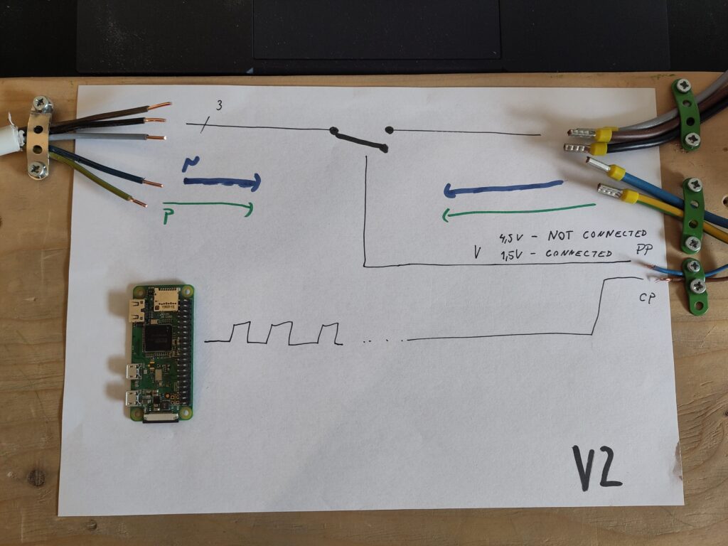
We will add some basic safety features to build up on the previous version.
We will look at the other non-AC pin on the chargebox socket. In our case, the blue wire is the Proximity Pilot. The voltage on that pin should tell us if the car is safely connected.
So, in version 2 of our charge box, we will take that information and use power relays to only power the end pins if the car is connected.
V3 – Listen to EV status
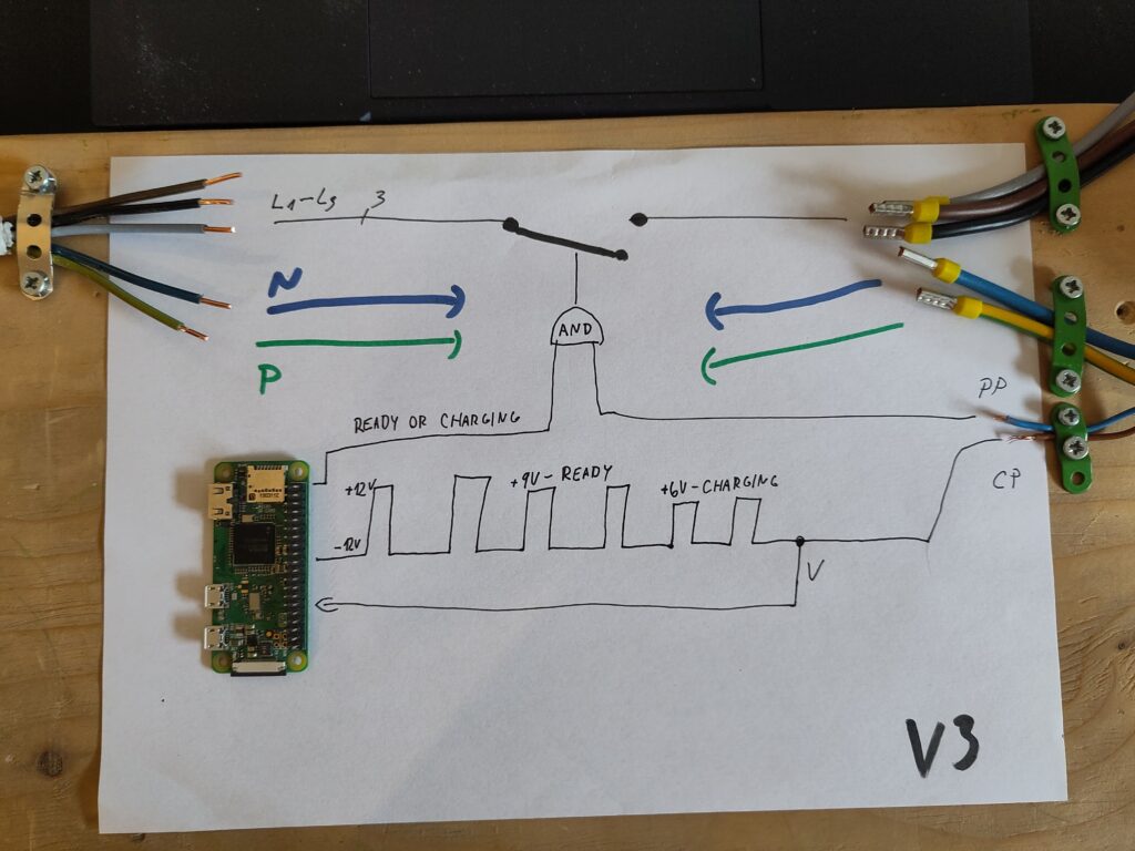
To wrap up our chargebox prototype, we will add one more feature. It turns out that the communication over the CP cable is very smartly designed to work both ways.
As we covered in V1, the duty cycle – the width of the rectangles in signal tells EV how much energy it can draw. EV on the other way can change the amplitude so the hight of the signal to tell back chargebox in what state the EV is.
There are several predefined voltage levels, but for our use case, we care mostly about Ready or Charging status. We will have to build a detection system, and if we detect the voltage dropping to 9 or 6 volts, respectively, we will close the power relays again to let the power through.
In the end, if the EV’s state is other than Ready or Charging OR the proximity pilot isn’t reporting a connected EV, we won’t provide power to the pins.
Summary
Now, I have a directional plan for approaching the charger. I am happy I could break it down into a few versions or steps rather than a big project with an uncertain end. There are still a bunch of questionmarks in my head about details, but I can’t wait to start experimenting with it and figure those out.